Modern product development demands more than just great design. It requires seamless data flow across every tool your engineering team uses.
When mechanical and electrical CAD systems operate as isolated islands, you're not just dealing with an IT headache. You're facing strategic barriers that slow launches, drain engineering productivity, and compromise product quality.
TL;DR: Multi-CAD PLM integrates data from multiple design tools (SolidWorks, Creo, NX, Altium, etc.) into a single source of truth, eliminating manual handoffs and version control chaos. Propel's Design Hub offers vendor-neutral, automated multi-CAD integration that respects your existing CAD investments.
What is Multi-CAD PLM?
Multi-CAD PLM is a product lifecycle management (PLM) approach that integrates data from multiple computer-aided design (CAD) systems—such as SolidWorks, Creo, NX, Altium, and AutoCAD—into a single, unified source of truth.
Unlike traditional PLM systems that prioritize one CAD platform, multi-CAD PLM treats all design tools as equal citizens, enabling seamless data flow across mechanical (MCAD), electrical (ECAD), and legacy or mixed-format design environments.
The Multi-CAD Reality
Manufacturers today work across multiple CAD environments—and for good reason.
Your mechanical team uses SolidWorks. Electronics relies on Altium or OrCAD. Legacy components live in Autodesk AutoCAD. Specialized work demands Creo or NX.
But here's what that reality looks like on the ground: When you switch suppliers, their CAD data arrives in different formats with inconsistent naming conventions.
You're building spreadsheets to reconcile part numbers.
You're manually cleaning up attribute mismatches between what SolidWorks exports and what your PLM expects.
You're cross-referencing three different Excel files to verify BOM accuracy before a release, and praying nothing falls through the cracks.
This isn't a technology problem to solve; it's a business reality driven by M&A activity, specialized design requirements, legacy system dependencies, and supplier ecosystems with their own preferred tools.
The crux of this challenge is that each CAD tool excels at its job but creates data silos that make maintaining a single source of truth nearly impossible.
The Hidden Cost of CAD-PLM Disconnection
1. Engineering Time Drain
Engineers spending hours manually exporting BOMs, reformatting data, and re-entering information into product lifecycle management (PLM) systems aren't designing better products. They're compensating for disconnected systems—time that should be invested in innovation, not data translation.
2. Version Control Chaos
Without seamless integration, tracking which CAD file version corresponds to which PLM item revision becomes manual guesswork. One mismatched file can cascade into manufacturing using outdated designs—resulting in scrap, rework, and delayed shipments.
3. Cross-Functional Visibility Gaps
When design data lives in isolated PDM systems, procurement, manufacturing, quality management, and marketing teams operate blind. This forces sequential handoffs instead of parallel collaboration, creating bottlenecks that slow your entire product development cycle and prevent stakeholders across the supply chain from accessing critical product information.
4. Manual Handoff Errors
Every manual data transfer introduces risk. A missing part, an incorrect attribute, or a forgotten attachment can ripple through your entire product lifecycle, causing delays and quality issues downstream.
Why Traditional Integration Approaches Fail
Many organizations attempt multi-CAD integration through:
- Point-to-point custom integrations — Brittle, expensive to maintain, and resource-intensive
- Manual export/import processes — Time-consuming, error-prone, and impossible to scale
- Single-CAD mandates — Ignore business realities and limit design flexibility
- Siloed PDM systems — Create disconnected islands of product data
These approaches fail because they don't address the fundamental need: a unified digital thread—a continuous, traceable flow of product data from design through manufacturing and beyond—that connects mechanical design, electrical design, and enterprise PLM into one seamless workflow.
The "Favorite Child" Problem with Legacy PLM
Traditional PLM vendors approach the design data challenge with a fundamental bias that drives up complexity and cost for most manufacturers.
Three Approaches to Design Data Integration
Across engineering setups, design data integration with PLM environments tends to fall into one of three approaches:
- Import/Export with Robust Mapping — Design data is exported from CAD software and imported into PLM using configurable mapping profiles
- Workflow-Based Publication — At specific triggers (like design release or validation milestones), engineering publishes a release candidate to the enterprise
- Native-First Sync — Deep, tightly-coupled integration built primarily for the vendor's own CAD platform, with every other CAD tool treated as a secondary citizen requiring expensive custom work to reach parity
PLM providers like PTC (Creo and Windchill), Siemens (NX + Teamcenter), and Dassault Systèmes (with CATIA and 3DEXPERIENCE) are structurally positioned to favor the third approach since they also develop and sell their own CAD systems, and their go-to-market naturally emphasizes that integration path.
The Corporate Umbrella Effect
When your PLM solution provider is under the same corporate umbrella as a major CAD vendor, an inherent bias emerges. While these vendors technically support different CAD systems, they inevitably prioritize their "favorite child"—their proprietary CAD platform.
Configuring a bidirectional sync solution that handles the preferred CAD system alongside other 'lesser children' commonly requires significant investment. Organizations pursuing this path often find they need:
- Specialized consultants with deep expertise in specific CAD data management tools
- Custom development to accommodate each additional CAD platform
- Ongoing maintenance as CAD and PLM versions evolve
- Infrastructure to support real-time synchronization
- Rigorous data integrity validation across multiple systems
Who This Approach Actually Serves
The bidirectional sync approach works well for a specific—and limited—type of manufacturer:
- Single-CAD environments with simple PDM setups
- Organizations fully committed to a single vendor's ecosystem (e.g., all Creo with Windchill, or all CATIA with 3DEXPERIENCE)
- Companies content with integration restrictions placed by their PLM giant's preferred CAD partnerships
- Enterprises with substantial IT resources dedicated to maintaining complex integrations
For these organizations, staying within a single vendor's product family can provide deep integration and minimize some complexity—provided you're willing to accept the limitations and costs that come with it.
The Unmet Need for Flexible Approaches
Propel Software takes a fundamentally different approach with its CAD-PLM solution, Design Hub.
Because Propel is not part of a corporate umbrella that includes CAD in the portfolio, the Design Hub solution has the capacity to work with all CAD vendors equally.
Design Hub therefore supports any setup or approach—multi-CAD or single CAD, simple or complex products—giving you the flexibility to meet your real needs rather than forcing you into an integration strategy that serves a vendor's broader product portfolio.
Bottom line: With Design Hub, your choice is not dictated by which CAD system a PLM provider wants to sell you.
Propel Design Hub: Unified Multi-CAD Integration
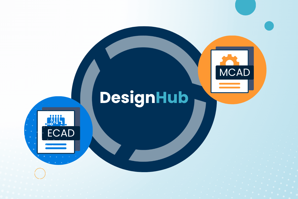
Design Hub integrates mechanical (MCAD) and electrical (ECAD) computer-aided design data into a unified digital thread. It streamlines workflows from design to release and makes product information accessible across your entire enterprise.
How Design Hub Works
Design Tool Integration
Design Hub connects to various MCAD and ECAD environments—on-premise or cloud-based. Integration with existing Product Data Management (PDM) systems via PDM connectors supports a CAD-agnostic approach that works with AutoCAD, Creo, SolidWorks, NX, and more.
Intelligent Data Ingestion and Review
Design Hub ingests design data through manual and automated flows. It rationalizes inputs from design tools and enables review against the current baseline. Engineers preview redlines (attributes, Bill of Materials, Approved Manufacturer List) and review files—including 3D models and visualization—before committing changes, ensuring data integrity before information enters your PLM system.
Automated Part Numbering
Design Hub automates part numbering governed by Propel, packaging part details, BOM, neutral files, and viewables together for review before they enter your product record. This eliminates manual number generation and ensures consistency across all design tools.
Workflow Automation
Design Hub automates key workflows with design tools, reducing effort and errors during part creation, detail and file updates, and BOM structure for release. Automated flows handle new part number requests and importing new designs.
Seamless Preview and Release
Only once reviewed and approved, changes move from the preview/staging side into the overall digital thread. Design Hub sessions, inputs, and change sets are preserved for audit purposes and validation. Reviewed data is added to change orders, approved, and released, maintaining full traceability throughout the product lifecycle.
The Path Forward
Product complexity is increasing. Development cycles are compressing. The ability to seamlessly integrate multi-CAD data with PLM isn't optional, it's critical for digital transformation.
Organizations managing this manually or through brittle point-to-point integrations face a competitive disadvantage.
Design Hub represents a fundamental shift in CAD-PLM integration. Rather than forcing engineering teams to adapt to PLM constraints or requiring expensive custom development, Design Hub creates a flexible, automated bridge that respects existing workflows while delivering enterprise-wide visibility and control.
Design Hub offers a path forward that:
- Respects your existing CAD investments by working with multiple design tools
- Reduces engineering burden through automation and intelligent workflows
- Accelerates time to market by eliminating manual handoffs and improving collaboration
- Maintains compliance with full traceability and audit trails
- Scales with growth whether you're adding product lines, acquiring companies, or expanding globally
- Optimizes your digital thread by serving as a vendor-neutral integration provider that connects design, engineering, quality management, supply chain, and ERP
The future of product development belongs to companies that move fast without sacrificing quality or control. Design Hub makes that possible.
Ready to centralize your design data and reclaim engineering hours? Request a demo of Design Hub today.
Frequently Asked Questions
Q: Why do manufacturers use multiple CAD systems?
Manufacturers use multiple CAD systems for several business reasons: M&A activity brings together companies with different design tools; specialized design requirements (mechanical vs. electrical) demand purpose-built CAD platforms; legacy product lines rely on older CAD environments; and supplier ecosystems often use their own preferred CAD tools, requiring data exchange across formats.
Q: What's the difference between multi-CAD PLM and traditional PLM?
Traditional PLM systems are often tightly coupled with a single CAD vendor (e.g., PTC's Windchill with Creo, or Siemens' Teamcenter with NX). Multi-CAD PLM solutions like Design Hub are vendor-neutral, treating all CAD platforms equally and enabling seamless integration without prioritizing one "favorite child" CAD system.
Q: What problems does multi-CAD integration solve?
Multi-CAD integration eliminates manual data translation, reduces version control errors, improves cross-functional visibility, and accelerates time to market by automating data flow between design tools and enterprise PLM systems.
Q: How does Design Hub handle data from different CAD systems?
Design Hub ingests design data from MCAD and ECAD tools (including SolidWorks, Creo, NX, AutoCAD, Altium, and others) through configurable mapping profiles and partner integrations, whether you're working with an existing on-prem PDM, a cloud PDM environment, or no PDM at all. It rationalizes inputs, enables engineers to preview changes against the current baseline, and automates part numbering and BOM creation before committing data to your PLM system.